
Design for Manufacturability: A Hardware Guide
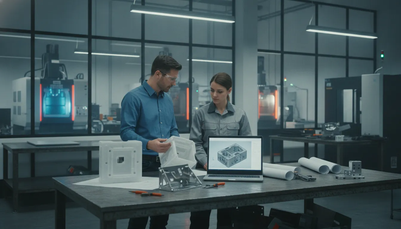
Design for manufacturability is the practice of shaping a hardware design so a chosen process can make it repeatedly, at the volume you intend, without avoidable rework. A model can look complete and still fail when the tool, the press, or the assembly bench meets it. Walls that look fine on screen can sink. A stamped bend can spring back. A die-cast boss can trap air. The review is not a second design project. It is a structured check of geometry, material, tooling, and assembly before money goes into production tools.
Call (407) 377-6899 to request a quote on a manufacturability review.
OEM product, engineering, and sourcing teams use this review when a new part, a revision, or a second source is close enough to build. The point is to decide which process the part actually belongs to, which features will fight that process, and which questions belong in the quote package. EMS Technologies treats that conversation as part of contract manufacturing. That means mechanical and electronic production, in-house engineering, and a program manager from the request for quotation through shipment.
What design for manufacturability covers
Design for manufacturability, often shortened to DFM, asks a practical question. Can this design be produced efficiently, consistently, and economically for a stated process, material, and volume? Boothroyd Dewhurst describes manufacturability in those terms, and the distinction matters. A part can be possible to make once and still be a poor candidate for production.
The review looks at the part the way the factory will see it. Process engineers care about how material flows, how a tool opens, how a cutter reaches a surface, and how an assembler holds the next piece. Design teams care about function, fit, and the drawing. Both views have to land in the same model before tooling starts.
DFM is not the same job as a design review meeting, and it is not a career description of a mechanical design engineer. The published guide to mechanical design engineering already walks from requirements through CAD, prototypes, and production release. This article stays on the manufacturability check itself: what to inspect, which process constraints usually bite, and when to bring manufacturing engineering into the file.
Separate the process from the preference
Teams often inherit a process because the last program used it. That is a preference, not a requirement. A bracket that needs a few hundred pieces and several machined datums may belong on a mill. The same shape at higher volume, with a stable wall and a draft-friendly exterior, may belong in a mold or a die. Write the volume, the material family, and the critical features down before anyone argues about the machine.
EMS groups mechanical work across tooling, injection-molded plastics, metal injection molding, metal stamping, die casting, and machining. Electronic work covers PCB assemblies, cable assemblies, magnetics, and turnkey assemblies. A DFM review names which of those paths the part is actually on. Mixing them in one sentence ("we will stamp or machine it") hides the constraint that will decide the tool.
When to run the review
The useful window is after the concept can be modeled and before the production tool is cut. Earlier than that, the team is still choosing the product. Later than that, every change is a tool change.
Three moments justify the work:
- Before the first hard tool. A prototype can hide problems that a production mold, die, or fixture will lock in. Review draft, wall thickness, bend relief, and datum schemes while the model can still move.
- When the process changes. Moving a machined part into molding, or a molded part into a multi-shot tool, changes the geometry the process will accept. Do not carry the old model forward unchanged.
- When a second source or a revision arrives. A new supplier does not inherit the tribal knowledge of the first tool. A revision that "only" moves a rib can change flow, knit lines, or press tonnage.
Industrial OEM programs are a natural fit for this timing. Industrial work is the largest share of EMS Technologies' business. Those products often combine a mechanical housing, a stamped or cast internal part, and an electronic assembly. Medical and automotive aftermarket programs raise the same geometry questions, with tighter documentation. Mil-aero work is outside the current focus.
What the quote package should already contain
A manufacturability review stalls when the file is incomplete. Send the model and the drawing, the CAD format and version, the material or alloy family, the annual volume, and the features that are truly critical. For a molded part, add color and the intended molding method. For a stamped part, add thickness. For a casting, add the alloy preference and the finish. The tooling discussion at EMS starts from that package: part concept or sample, drawing or model, intended process, and mold or die expectations.
Check the design against the real process
Generic DFM slides list "simplify the part." That advice is true and useless until it is tied to a process. The checks below follow the processes EMS actually runs. They are review questions, not a tolerance promise and not a substitute for the process-specific design notes already published for stamping and molding.
| Process | What the review should challenge | What to put in the file |
|---|---|---|
| Injection molding. | Wall thickness, draft, ribs, bosses, and undercuts. Also ask whether the part needs one shot or more. | Material, grade, and color. Note whether 2-shot, 3-shot, insert, or gas-assisted molding is in play. |
| Metal stamping. | Bend radii and hole-to-edge distance. Also ask which operations could live in one die. | Drawing or sample, plus material and thickness. The stated stock range runs from under 0.001 inch to 0.25 inch where it fits the part. |
| Die casting. | Section thickness and draft. Also flag features that will need machining after the shot. | Alloy family, such as aluminum, zinc, or a copper alloy. Add critical dimensions and the finish. |
| Machining. | Reach and setups. Also flag features that force a tool change or a second holding method. | The 3D file and the material. Mark which surfaces are datums and which are cosmetic. |
| Tooling. | Whether the tool life and the part geometry agree. | CAD format and version, the intended process, and the working life you expect from the mold or die. |
Injection-molded plastics
Start with geometry, material, color, and application. EMS molds custom plastic parts on computer-controlled equipment and will discuss 2-shot, 3-shot, insert, and gas-assisted methods when the part calls for them. Material families on the service page include acrylic, polycarbonate, PBT and PET, polypropylene, PVC, thermoplastic elastomers, nylon, and others. Ask whether a uniform wall is realistic. Ask whether a rib is carrying structure the wall should carry. Ask whether an insert is required, or whether it is a leftover from a machined prototype.
Do not treat a published press range as a promise for your part. Confirm the machine, the material, and the tool together. A value-engineering example on the molding side, such as adding ribs or moving an enclosure toward a higher ingress rating, is an illustration of design work. It is not a rating EMS applies to every housing.
Metal stamping
Stamping reviews start from a drawing or a sample. EMS design engineers and toolmakers use CAD/CAM to plan punching, bending, forming, blanking, and piercing, and they can combine several of those operations in one die. The useful DFM question is which of those operations are fighting each other. A hole too close to a bend belongs in the review, not in the first production lot. So does a flange with no relief, or a thickness outside the stated stock range of under 0.001 inch through 0.25 inch.
Name the metal. The page lists copper, beryllium copper, phosphor bronze, brass, spring and carbon steel, stainless, aluminum, nickel, and others. Thickness and temper change springback. If the part also needs resistance spot welding or a small assembly, say so in the same brief. Leaving that for a second supplier splits a problem the die could have solved.
Die casting and machining
High-pressure die casting at EMS covers aluminum, zinc, and copper alloys, with engineering input on material, part geometry, and the finish that follows the shot. The review should separate surfaces the die can make from surfaces that need machining afterward. Casting a feature that must be milled anyway adds a handling step. Machining a feature the die could hold adds cycle time.
Machining covers milling and turning for metal and plastic parts, including three-, four-, and five-axis work and wire EDM. A DFM pass on a machined part is mostly about setups. Every time the part is unclamped and re-indicated, you add variation and time. Mark the datums. Call out which faces are cosmetic. If a 3D file is the master, say so, and send the format the shop can open.
Tooling is part of the design
The tool is not a later purchasing task. EMS builds the tooling and mold-making plan around the part, from concept through computerized prototyping and CNC toolmaking. The objective stated on the tooling page is to shorten development time while meeting the mold specification and the working life you need. That only works if the part geometry, the CAD format and version, and the production quantity are in the same conversation as the steel.
For smaller complex programs, tooling can start with development and a test series in Taiwan. The tool can then move to China for production. Larger tools may be built and tested in China. That routing is a project decision, not the path for every program. Ask for it when the part is small and complex. Do not assume it.
Assembly and the electronic half of the product
A part-level DFM review can still ship a product that is hard to build. Industrial hardware often joins a molded or cast housing to a board, a cable, and a wound component. The assembly check asks who holds the unit, which fastener or snap is blind, and which test happens before the cover goes on.
EMS runs that electronic work in-house. PCB assemblies include design-for-manufacturability support. Cable work covers standard and custom assemblies and wire harnesses. Magnetics include inductors, transformers, sensors, and coils. Turnkey assembly then carries PCB design, parts procurement, electronic assembly, testing, and final packaging. If the mechanical model ignores the connector keep-out or the harness path, the housing DFM is incomplete.
Quality controls sit on the same path. The homepage describes design-for-manufacture review before production, inspection during assembly, and functional testing with yield tracking and revision control. ISO 9001:2015 is the documented quality certification for production management of electro-mechanical products at the certified entity. Do not read a market served, including medical or automotive, as an extra certification.
What not to fold into this review
Keep the check narrow so it stays useful:
- Partner selection, scorecards, and contract terms belong in their own conversations.
- A design-review meeting has its own agenda. This article is the manufacturability content you bring into that meeting, not the agenda itself.
- Process handbooks for stamping or molding own the detailed geometry rules. Use those pages when the process is already chosen. Use this review to confirm the process and the handoff.
- Prices, minimum order quantities, and lead times are not published. A DFM note can say a feature adds an operation. It cannot quote the operation.
How EMS runs the handoff
The homepage sequence is the right shape for a manufacturability handoff. Define the project. Engineer and prepare. Build and verify. Package and deliver. A dedicated program manager coordinates the work from the first request for quotation through shipment, which keeps the DFM notes from dying in a slide deck.
In practice, the engineering step is where design support, manufacturability, prototyping, and materials meet. Design and engineering at EMS covers systems, electrical, mechanical and industrial design, and software and embedded work. Mechanical and industrial design on that page includes 3D CAD, product rendering, enclosure design, and tooling and fabrication support. Bring the open questions with the model. A complete specification is not a requirement to start.
TQRDC, the five priorities of technology, quality, response, delivery, and cost, is the lens EMS uses on that handoff. Technology means the engineering input that connects your design to a real material and process. Quality means the controls on materials, manufacturing, tooling, and packaging. None of those priorities replaces a drawing.
A practical review sequence
- Name the process and the volume. One primary process, one annual quantity, one material family. If two processes are still open, run two reviews. Do not average them.
- Mark the features the process must hold. Datums, sealing surfaces, mating faces, and any dimension that fails the product if it drifts.
- Walk the tool. Ask how the mold or die opens, where the material enters, and which features need a slide, a second hit, or a later machine cut.
- Walk the assembly. Include the board, cable, magnetics, and test access if the part is a housing or a chassis.
- Write the changes back into the model. A review that lives only in email will not survive the next revision. Agree on the reporting cadence for tool build and first shots.
Program management is the place those notes stay attached to the job. The program page describes a single point of contact across quotation, engineering, procurement, testing, and shipment. Use it when the DFM actions cross more than one process, which they usually do on an electromechanical build.
Questions worth asking before tooling
These are the questions that change a tool, not the questions that fill a status meeting.
- Which single process is this part designed for, and what volume makes that process the right one?
- Which features are critical to function, and which are leftovers from a prototype method?
- Does the wall, the bend, or the section match what that process can hold without a secondary operation?
- What CAD format and version will the toolmaker open, and who owns the master model?
- If the part is molded, is a second shot, an insert, or gas assist actually required?
- If the part is stamped or cast, which operations can live in the tool, and which need welding, machining, or assembly afterward?
- Where does the electronic assembly sit, and can it be tested before the cover closes?
- What should the first-shot or first-article report include, and who signs a change after the tool is cut?
Answer them in writing. A verbal "the molder will figure it out" is how draft, texture, and gate location get decided by the tool instead of by the product.
Frequently asked questions
What is design for manufacturability?
Design for manufacturability is the engineering check that makes a product practical to build on a stated process, in a stated material, at a stated volume. It looks at geometry, tooling, and assembly before production tools are cut, so the factory is not the first place a design problem shows up.
How is DFM different from design for assembly?
DFM asks whether each part can be made well. Design for assembly asks whether those parts can be put together well: access, orientation, fastening, and test. A housing can mold cleanly and still be a poor assembly if the board or the harness has no path. Review both before the tool is released.
When should an OEM request a manufacturability review?
Request it when the model is real enough to discuss and before the production mold, die, or fixture is built. Also request it when you change process, add a second source, or revise a feature that affects flow, bending, or machining. Earlier concept work is product definition, not DFM.
What should we send with the review request?
Send the drawing or 3D model with the CAD format and version, the material or alloy, the annual volume, and the features that must be held. Add color and molding method for plastics, thickness for stampings, and alloy and finish for castings. Include related welding, machining, or electronic assembly if they belong to the same unit.
Does a manufacturability review replace a process design guide?
No. A DFM review decides whether the design and the process agree, and it records the handoff into tooling and assembly. Detailed rules for one process, such as stamping geometry or molding wall design, stay with that process guide. Use the review to choose the path, then use the guide to finish the model.
If a model is ready and the process is still an open question, call (407) 377-6899 or book a meeting. Bring the drawing, the material, and the volume. Walk the issues before tooling starts.