
Electronic Product Design and Engineering: A Practical Guide
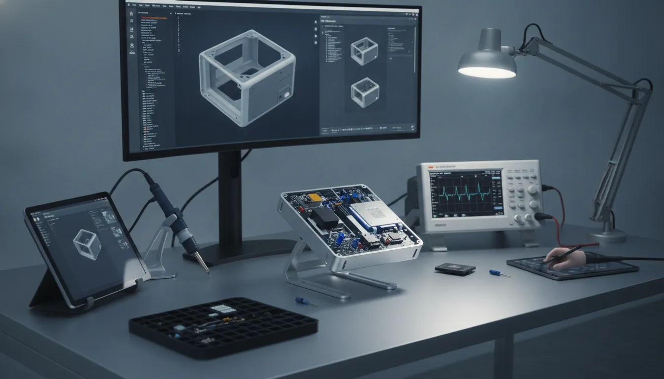
A prototype that works on a desk is only one step toward a product customers can use and manufacturers can build reliably. The design also needs to meet performance and safety requirements, fit within its enclosure, use available components, and support repeatable assembly. Electronic product design and engineering brings these needs together, connecting technical decisions with testing and manufacturing realities. When teams involve the right specialists early, they can identify constraints while there’s still time to address them. This guide covers the key development phases, the people involved, and practical ways to prepare an electronic product for production.
Key Takeaways
- Set shared requirements early: Give engineering, sourcing, testing, and manufacturing teams clear goals, decision owners, and a process for tracking changes.
- Use prototypes and pilot builds to guide decisions: Test against defined criteria, document issues, and verify revisions before increasing production.
- Connect design choices to production needs: Review components, materials, tooling, assembly, and documentation together, with manufacturing input before the design is finalized.
What Is Electronic Product Design and Engineering?
Electronic product design and engineering turn product requirements into a device that works reliably and can be made consistently. The process brings together electrical and mechanical design, firmware, testing, sourcing, and production planning. Coordinating these areas early helps teams make informed choices about performance, cost, and manufacturing.
Turn product requirements into a functional, manufacturable device
Requirements define what a product needs to do, who will use it, and the conditions it must meet. Engineers translate them into design decisions, including circuit architecture, component choices, enclosure dimensions, and assembly methods. The goal is to create a product that performs as intended and can be produced consistently, not just a prototype that works once.
Manufacturing considerations can shape a design from the start. PCB layout, component availability, enclosure construction, and access for assembly may affect production cost and complexity. A practical guide to design for manufacturing explains how early choices can influence the transition from design to production. Reviewing these factors while requirements are still taking shape gives teams more room to make useful adjustments.
Integrate electronics, firmware, mechanical design, and production planning
An electronic product is a system of connected parts. The PCB needs to fit inside the enclosure, firmware must work with the selected components, and mechanical features need to support both product use and assembly. Teams also need to consider heat, power, cable routing, and access for testing.
These dependencies make collaboration essential. Electrical, firmware, mechanical, and manufacturing teams should share requirements and review design choices together, rather than working through isolated handoffs. Regular discussions help surface conflicts while there is still time to address them. ZEISS’s guidance on engineering collaboration highlights the value of combining expertise to balance customer needs with technical feasibility. An integrated manufacturing partner such as EMS Technologies can also connect mechanical and electronic services with production planning.
Involve manufacturing experts early to identify cost, supply, and production constraints
Manufacturing experts can identify concerns that may be easy to miss during an early design review. They may flag components with limited availability, tight tolerances that could add cost, or assemblies that require extra steps. Discussing these issues before finalizing the design gives the team more options and can help prevent late revisions.
Bring manufacturing, sourcing, and engineering teams together at regular design reviews. Use those meetings to check tooling, materials, production capacity, and assembly methods against the product requirements. Keep a record of open questions and decisions so the team can follow up as the design changes. EMS Technologies’ overview describes its in-house engineering and program management support, which helps connect development decisions with manufacturing needs.
What Are the Main Phases of Electronic Product Development?
Electronic product development turns a product idea into a design that works reliably and can be manufactured consistently. The phases often overlap, so teams should share information early and revisit decisions as requirements, designs, and test results evolve.
Define user needs, requirements, constraints, and success measures
Start by identifying who will use the product, what they need it to do, and where they will use it. Translate those needs into clear requirements, such as operating temperature, battery life, size, connectivity, service life, and applicable safety standards. Specific requirements give design, engineering, and manufacturing teams a shared reference point.
Set success measures early, too. These might include target cost, performance, production volume, or ease of assembly. Involve the people responsible for design and production while defining these measures, so the requirements reflect both user expectations and practical constraints. Strong collaboration between engineering disciplines helps teams share expertise and address potential issues before they become expensive design changes.
Assess feasibility, architecture, costs, schedule, and technical risks
Next, evaluate whether the product can meet its requirements within the available budget, schedule, and technical capabilities. Compare system architectures, estimate component and tooling costs, and check the availability of critical parts. Identify risks such as heat, power consumption, signal interference, and components that may be difficult to source.
Use this assessment to make informed trade-offs before detailed design begins. Electronic design automation tools can help engineers develop and analyze circuit designs, making it easier to identify potential problems early. A market overview of electronic design automation software notes demand for tools that help reduce design flaws and support faster development. Document key assumptions, risks, owners, and decision dates so the team can track them throughout the project.
Design and integrate hardware, firmware, enclosures, and mechanical interfaces
Hardware, firmware, and mechanical design need to progress together. Electrical engineers select components and lay out the printed circuit board, while firmware developers define how the device responds to user actions and operating conditions. Mechanical designers plan the enclosure, mounting points, connectors, and access for assembly or service. A change in one area can affect the others: component choices influence power and heat, while enclosure dimensions can limit board space or antenna performance.
Use digital models and prototypes to check how parts fit and function before committing to production tooling. Digital twin technology lets teams test virtual product models under simulated conditions. Review interfaces, tolerances, and dependencies regularly to catch conflicts early. Involving a manufacturing partner with integrated engineering and production services can also help teams account for tooling, materials, and assembly needs during design.
Verify the design, test and refine it, and prepare it for production
Testing confirms whether the product meets its requirements in real conditions. Depending on the device, tests may cover function, electrical performance, safety, reliability, environmental limits, and usability. Compare results with the success measures defined at the start, document defects, and assign clear follow-up actions. Test each revision to make sure a fix does not introduce a new issue.
When the design is stable, prepare the documentation needed for consistent production, including approved drawings, a bill of materials, specifications, test procedures, and assembly instructions. A pilot build can expose problems that prototypes may miss, such as difficult assembly steps or inconsistent part fit. Regular feedback between design and engineering teams helps turn test findings into practical revisions before production scales.
How Do Electronics, Firmware, and Enclosures Work Together?
An electronic product works as a system. The PCB, firmware, and enclosure all influence one another, so a change in one area can affect the others. A different component may alter power use or heat output; that could require a change to the enclosure or assembly process. Teams that coordinate these decisions early can find conflicts while they are still manageable.
Design the PCB, select components, and plan for power, heat, and space
Begin with the product’s requirements, then use them to guide the PCB layout and component choices. Consider power needs, heat output, available board space, and how the PCB will fit inside the enclosure. Check component availability and lifecycle, too. A part that is difficult to source can affect production timing and cost.
Electronic design automation tools help engineers create and review circuit designs before manufacturing. Still, the design needs input from mechanical, sourcing, and manufacturing teams. They can flag components that are hard to source or assemble, and identify fit concerns early. Reviewing the design with a manufacturing partner such as EMS Technologies can help connect electronic requirements with mechanical and production needs.
Develop and test firmware alongside hardware
Firmware controls how a device responds to inputs, communicates, and performs its core functions. Because it depends on the hardware, teams should develop and test firmware alongside the PCB rather than waiting until the board design is finished. Early testing can confirm that processors, sensors, and communication components support the product’s intended behavior.
Set regular check-ins between firmware and hardware teams. A component change may require firmware updates, while testing may reveal that the hardware needs a different feature or configuration. Early integration gives teams time to address these dependencies before they complicate later work. Establishing feedback loops between product and design teams helps surface concerns and keep technical choices aligned, as outlined in this guide to engineering collaboration.
Coordinate enclosure materials, tolerances, tooling, and assembly
The enclosure protects the electronics and affects product size, weight, durability, heat management, and assembly. Its dimensions must accommodate the PCB, connectors, cables, fasteners, and any required access points. Tolerances matter, too: parts need enough clearance to fit together reliably without compromising alignment or function.
Involve mechanical and manufacturing experts before finalizing the enclosure. A design that works in a digital model may be difficult to mold, machine, or assemble at production volumes. Review material choices, tooling requirements, fastening methods, and assembly access while changes are still practical. Understanding engineering limits early helps teams create designs that are both functional and producible. The services offered by EMS Technologies include molded plastics, metal parts, machining, and assembly, which can help teams consider these requirements together.
Manage interfaces and dependencies to prevent downstream problems
Interfaces are where components or teams connect. They may include a cable-to-board connector, a PCB mounting point, or a firmware function that depends on a particular component. Document each interface clearly, including dimensions, electrical requirements, ownership, and assumptions. Shared drawings and revision records help teams use the same information throughout development.
Track dependencies as well. For example, enclosure dimensions may depend on the final PCB layout, while a firmware feature may rely on a specific sensor. Assign owners to decisions and review the impact of proposed changes before approving them. Clear handoffs make parallel work easier and reduce avoidable surprises. Teams can use practical design and development collaboration practices to clarify what each group needs from the others and keep related decisions visible.
How Can Teams Coordinate Design and Engineering?
Coordinating electronic product development takes more than sharing files. Electrical, firmware, mechanical, test, sourcing, and manufacturing teams need to work from the same requirements and understand how their decisions affect one another. A component change, for example, can alter the PCB layout, enclosure dimensions, firmware behavior, testing plan, and supplier schedule.
Set up collaboration before the design is locked. Agree on how teams will share updates, raise risks, approve changes, and track decisions. Regular cross-functional reviews help surface mismatches while they are still manageable. Clear ownership and accurate records also make it easier to move from design into prototyping and production without losing important context.
Involve electrical, firmware, mechanical, test, sourcing, and manufacturing teams early
Bring the people who will design, test, source, and build the product into planning discussions early. Electrical and firmware engineers can identify interface, power, and performance needs. Mechanical engineers can assess fit, materials, and enclosure constraints. Test teams can define how the product will be verified, while sourcing and manufacturing specialists can flag component availability, tooling, and production concerns.
This early input helps the team balance product goals with technical and manufacturing realities. ZEISS describes how engineering collaboration can support product quality. Set regular checkpoints, share current design files, and give each discipline a clear way to raise concerns before decisions become costly to change.
Set clear roles, decision owners, and shared requirements
Define who owns each decision, who reviews it, and who needs to be consulted. An electrical engineer might lead component selection, for example, while a mechanical engineer owns enclosure decisions. A program manager can track cross-functional actions and dependencies so that questions do not linger without an owner.
Create one shared set of product requirements covering function, performance, interfaces, cost, schedule, and production needs. When a requirement changes, record the update and tell everyone affected. Accessible, consistent communication makes it easier for teams to work toward the same goals, as outlined in UXPin’s product development collaboration guidance.
Document design decisions, risks, revisions, and test results
Keep a clear record of major design decisions, open risks, drawing revisions, and test results. Note why a decision was made, which alternatives the team considered, and which requirements it affects. This context helps engineers and manufacturing partners review the design, understand trade-offs, and investigate issues later.
Store specifications, schematics, CAD files, bills of materials, and test reports in a shared, controlled location. Use a versioning process that makes the latest approved files easy to identify, so teams do not build from outdated information. Hyland recommends documenting communication, file sharing, and decision-making processes to help keep collaborators aligned.
Use program management to align schedules, teams, and suppliers
A program manager connects technical work to the overall project plan. They track milestones, dependencies, decisions, and risks across design, testing, sourcing, tooling, and production. A PCB revision, for instance, may affect firmware testing, enclosure fit, component orders, and the timing of a pilot build. A shared schedule helps teams see these connections and respond before delays spread.
Set a regular review rhythm, assign owners to action items, and update the plan when new information changes priorities. Include suppliers and manufacturing partners in discussions when their capabilities or lead times affect design choices. EMS Technologies offers engineering, program management, and manufacturing services to support coordination across mechanical and electronic production.
How Do Prototyping and Testing Reduce Development Risk?
Prototypes and tests help teams check whether a product works as planned before they commit to full production. They can reveal problems with performance, assembly, materials, or how hardware and firmware interact. Finding those issues early gives the team more options to address them, while design changes are generally easier to make than after tooling and production processes are in place.
Testing also creates a shared basis for decisions. Electrical, firmware, mechanical, quality, sourcing, and manufacturing teams can review the same results, agree on priorities, and track what needs to change. A documented process makes it easier to verify that revisions solved the original problem and did not create another one. Working with a manufacturing partner early can connect prototype findings to tooling, components, and assembly requirements. EMS Technologies’ integrated manufacturing services bring mechanical and electronic capabilities together to support that process.
Build prototypes to assess fit, function, performance, and usability
A prototype gives the team a physical or working model to evaluate. For an electronic product, build and review the PCB and enclosure together. This can reveal whether components fit, connectors are accessible, the product can be assembled as intended, and heat has a path to dissipate. Functional prototypes can also help confirm that firmware and hardware behave correctly together.
Choose the prototype method based on what you need to learn. A CAD model or 3D-printed part may be enough to assess size and fit, while a CNC-machined enclosure or functional build can help evaluate performance and features such as water or dust resistance. As electronic product design guidance notes, developing the enclosure alongside the PCB can help teams catch fit and assembly issues before production.
Test against requirements, safety needs, reliability targets, and applicable standards
Start with clear requirements: what the product must do, the conditions it needs to withstand, and the safety and reliability targets it must meet. Turn each requirement into a test with a defined method and pass criteria. This helps teams identify gaps systematically instead of relying on general impressions from a prototype review.
Standards and certification needs depend on the product and its intended markets. Requirements may include FCC, CE, RoHS, UL, or relevant ISO standards. Identify likely obligations early and confirm them with qualified specialists, since design changes after certification can trigger further review or testing. Keep test plans, results, and approvals together so the team can see what has passed and what remains open. The electronic product design guide also recommends planning certification around the final design.
Track defects and use test results to guide revisions
When a test uncovers a defect, record enough detail for the team to reproduce and investigate it. Include the product and build version, test conditions, observed behavior, frequency, and severity. Assign an owner and track the issue through investigation, corrective action, and retesting. This makes it clear whether a revision resolved the problem.
Share results across disciplines, since one issue can have several possible causes. A connector that does not align, for example, may involve the PCB layout, enclosure geometry, or assembly sequence. Regular communication helps teams compare findings and identify the right fix. Engineering collaboration can bring manufacturing considerations into design discussions early, when teams still have room to adjust the product or process.
Run pilot builds to find product and process issues before scaling
A pilot build is a limited run that tests how the product and its manufacturing process perform together. It can show whether units meet specifications consistently, assembly steps are repeatable, and suppliers, tooling, and work instructions are ready for a larger run. It also gives teams a chance to evaluate hardware and firmware interactions under realistic build conditions.
Review pilot results with engineering, quality, sourcing, and production teams. Track defects, assembly delays, and variation between units, then decide whether to revise the product, the process, or both. Some projects need multiple pilot rounds to verify that fixes work across builds. Treat the pilot as a learning stage, not just a final checkpoint: use its findings to refine production plans before committing to scale.
What Is Design for Manufacturability, and Why Does It Matter?
Design for manufacturability (DFM) means planning a product so it can be made reliably and efficiently while meeting its functional, performance, and quality requirements. It brings production considerations into design decisions early, when teams have more flexibility to adjust parts, materials, and processes.
For electronic products, DFM applies to the whole build, not just the circuit board. Enclosures, cables, tooling, assembly steps, and testing all influence how smoothly a design moves into production. A DFM review can help teams spot unnecessary complexity and production risks before they lead to delays or costly changes.
Simplify parts and assembly without compromising requirements
Start by reviewing each part, fastener, connector, and assembly step. Ask whether it is needed to meet the product’s requirements, and whether a simpler option could deliver the same function. Reducing unique parts or using standard components may make sourcing and assembly more straightforward.
Simplicity should not come at the expense of performance, reliability, safety, or service needs. For example, combining functions into one component might reduce assembly steps, but only if the combined part meets the same requirements and can be produced consistently. Involving manufacturing engineers in these decisions helps teams assess practical trade-offs. DFM guidance offers examples of how simpler designs and standard components can support production.
Consider tooling, materials, tolerances, and component availability early
Materials and tooling affect product performance as well as manufacturing cost and complexity. An enclosure material, for instance, can influence strength, heat resistance, and molding requirements. Tolerances matter, too. If a specification is tighter than the product’s function requires, machining and inspection may become more demanding than necessary.
Check component availability while the design is still taking shape. Parts with long lead times or limited sourcing options can create schedule risks and make production harder to sustain. Early input gives teams time to compare alternatives and understand the effects of each choice. EMS Technologies offers services across tooling, plastics, metalworking, machining, and assembly, supporting manufacturing considerations across a product’s components.
Design PCB and cable assemblies for efficient, repeatable production
A PCB must work electrically, but its layout should also support assembly, inspection, testing, and integration into the finished product. Component placement, routing, connector locations, and access for test equipment can all affect how easily a board can be produced and checked.
Apply the same practical thinking to cable assemblies. Choose connectors that suit the product’s electrical and mechanical needs, and plan cable routing so technicians can install and inspect assemblies without unnecessary difficulty. Confirm that cables, boards, and connectors fit the enclosure and align with its interfaces. Reviewing these details together can prevent rework later. Electronic product design guidance explains why manufacturing needs should inform PCB placement and routing decisions.
Review designs with engineering, sourcing, and manufacturing teams
A useful DFM review brings together the people who design, source, assemble, and test the product. Engineering can clarify functional requirements, sourcing can flag availability concerns, and manufacturing teams can identify parts or steps that may be difficult to produce. Sharing this input early helps teams make informed trade-offs before decisions are locked in.
Set review points at key design stages, assign owners to open questions, and keep requirements, revisions, and decisions documented in a shared record. That gives each team a clear view of what has changed and why. EMS Technologies combines in-house engineering and program management with manufacturing services, supporting coordination from design through production. Engineering collaboration can help teams share expertise and identify issues earlier.
How Do Teams Prepare Electronic Products for Production?
A product that works in a prototype is not automatically ready for a production line. Teams still need to make sure every part can be sourced, every assembly step is clear, and each finished unit can meet the same requirements. Preparing for production means bringing engineering, sourcing, quality, and manufacturing decisions together before the first full build.
Start by treating production readiness as a coordinated process, not a final paperwork task. Confirm that the design is stable enough to build, identify the people responsible for each decision, and agree on how the team will manage revisions. Then review the product as a complete system: its PCB, firmware, cables, enclosure, mechanical parts, packaging, and assembly process. A change to one element can affect fit, performance, cost, or delivery schedules elsewhere.
It also helps to involve manufacturing specialists while the team still has time to act on their feedback. They can flag unclear drawings, difficult assembly steps, long-lead components, or tooling needs before these issues disrupt a production schedule. EMS Technologies’ manufacturing services span mechanical and electronic processes, including tooling, molded plastics, metalworking, PCB and cable assemblies, and turnkey assembly. The right preparation depends on the product, but the goal is consistent: give everyone involved the information and support needed to build it reliably.
Finalize drawings, bills of materials, specifications, and work instructions
Before production begins, collect the latest approved product documents in one controlled set. This may include engineering drawings, PCB design files, a bill of materials (BOM), product specifications, and assembly and inspection instructions. Check that the BOM matches the approved design and that each document shows its current revision. An outdated component number or unclear tolerance can lead to sourcing mistakes, assembly delays, or inconsistent products.
Make work instructions specific enough for operators to follow without guessing. Include the assembly sequence, required tools, key inspection points, and any handling precautions. Assign an owner to each document and define how updates are reviewed and shared with engineering, sourcing, and manufacturing. This guide to electronic product design for manufacturing outlines documentation teams may need as they prepare a product for production.
Coordinate suppliers, tooling, molded plastics, metal parts, and assemblies
Many electronic products depend on parts made through different processes, such as PCB fabrication, cable assembly, injection molding, machining, and metal stamping. Align suppliers on the approved design revisions, delivery milestones, specifications, and quality expectations. Confirm lead times for components and custom tooling early. A delay in a mold, die, or critical electronic component can hold up the entire build.
Build a complete cost estimate rather than relying on the BOM total alone. Account for tooling, prototypes, testing, packaging, shipping, duties, and warehousing where relevant. Ask suppliers to identify long-lead or single-source items, then assess possible alternatives with engineering before a shortage forces a rushed decision. When several processes contribute to one finished product, clear ownership and regular communication help teams manage handoffs and keep schedules aligned.
Plan quality controls, capacity, sourcing, and engineering change management
Set quality checks before production begins. Define acceptance criteria for incoming parts, in-process assembly, and finished products, and confirm that inspection and test methods reflect the product requirements. Pilot builds help teams check product performance and repeatability while the volume is still manageable. Record problems, assign owners, and verify that corrective actions work before increasing production.
Review supplier capacity against expected demand, and track component availability and obsolescence risks. Design changes may be necessary, but every revision needs a clear path from approval to production. Use an engineering change process to record what changed, why it changed, which parts and documents are affected, and when the update takes effect. This gives sourcing and manufacturing teams time to respond and helps prevent outdated parts or instructions from reaching the production line.
Assess integrated support for PCB, cable, mechanical, and turnkey assembly
Look beyond the PCB when reviewing production support. A complete product may also need cable assemblies, molded enclosures, machined or stamped parts, and final assembly. If separate suppliers handle each element, your team may need to coordinate additional schedules, revisions, and quality requirements. Map the suppliers, processes, and handoffs involved so you can spot gaps before the first production run.
Ask manufacturing partners which capabilities they provide directly, how they manage outside suppliers, and who will coordinate the program. Clarify how they handle documentation, inspections, and engineering changes, too. EMS Technologies offers integrated mechanical and electronic manufacturing services, including PCB and cable assemblies and turnkey assembly. The right arrangement depends on your product’s needs and your internal resources, so compare the support available with the work your team is prepared to manage.
Which Challenges and Trends Should Teams Plan For?
Electronic product teams must balance technical requirements with people, schedules, component supply, and production needs. A decision that seems small during design can affect tooling, assembly, testing, or delivery later. Planning for common challenges early helps teams spot trade-offs and make changes while they still have options.
Address skill and resource gaps with clear ownership and specialist support
Electronic product development brings together electrical, firmware, mechanical, test, sourcing, and manufacturing expertise. Some companies may not have every specialty on staff, or their experts may be committed to other projects. Identify the skills each phase requires, assign owners for key decisions, and flag resource gaps that could affect timing or product requirements.
Bring specialists into discussions before designs are finalized, especially when a choice could affect tooling, assembly, or component selection. Early input helps teams check assumptions and identify constraints before they lead to costly revisions. Clear communication and program management also help keep responsibilities, decisions, and dependencies visible across disciplines.
When a project needs additional engineering or production capacity, an experienced manufacturing partner can offer practical support. EMS Technologies’ integrated services span mechanical and electronic manufacturing, with engineering and program management support throughout the process.
Control scope changes and manage component availability and obsolescence
A change to a feature or specification can affect the circuit board, firmware, enclosure, tooling, testing, cost, and schedule. Before approving a change, assess its impact across the whole product, not only the team requesting it. Document the reason, decision owner, affected requirements, and updates needed to drawings, bills of materials, and test plans.
Component availability needs the same level of attention. Parts may become difficult to source or reach end of life, putting production plans at risk. Work with engineering and sourcing teams to identify critical components, evaluate alternatives, and determine what testing a replacement requires. Keep the bill of materials current and use a defined process to review and approve substitutions.
Regular feedback between design and manufacturing teams can reveal issues while there is still time to address them. Early engineering collaboration helps teams identify mismatches before they lead to expensive revisions or production delays.
Plan for miniaturization, connected-device needs, and growing product complexity
Smaller products leave less room for components, connectors, batteries, and heat management. Miniaturization can also make board layout, assembly, and inspection more demanding. Set size, power, thermal, and performance requirements early, then review how they affect one another. A change to one constraint can create trade-offs elsewhere in the device.
Connected products bring additional requirements, such as wireless performance, firmware updates, data handling, and compatibility with other systems. Define the functions the product must support and how the team will verify them. Test hardware and firmware together early, rather than treating connectivity as a feature to add after the core design is complete.
As products become more compact and complex, teams need to coordinate PCB layout, component selection, enclosure design, and assembly. Trends in electronic design automation reflect the growing demand for accurate design of miniature electronic components.
Consider repairability, materials, and sustainability during design
Repair and end-of-life needs are easier to address before materials and assembly methods are set. Consider which components may need replacement, how technicians will access them, and whether the product can be disassembled without damaging parts. These decisions can influence fasteners, enclosure design, adhesives, and service documentation.
Material choices also involve trade-offs. Evaluate durability, availability, manufacturing requirements, and opportunities for reuse or recycling. A material that performs well in one area may affect cost, weight, or ease of repair. Involve design, sourcing, and manufacturing teams so they can compare options against product requirements.
Designing for repair and recycling can help extend product life and reduce electronic waste. The growing focus on repairable consumer electronics is a reminder to consider service and material choices early, rather than after production begins.
Resolve pilot-build issues through root-cause analysis and iterative improvements
A pilot build shows how a design and production process perform under realistic conditions. It may reveal assembly difficulties, fit problems, inconsistent test results, or unclear work instructions. Record each issue in enough detail to reproduce it, including the affected part or process, build conditions, and observed result.
Investigate the root cause instead of relying on a quick fix that could hide the underlying problem. Review design files, component specifications, tooling, assembly steps, and test methods with the people closest to the issue. Assign an owner to each corrective action, track it through verification, and update documentation when a change is approved.
Repeat builds can confirm that a fix works without creating new problems elsewhere. Transparent communication between design and engineering teams supports this cycle of testing and refinement. Collaboration during implementation helps teams turn pilot-build findings into practical improvements before production scales.
Which Roles and Skills Support Product Development?
Electronic product development brings together people with different specialties. Teams need technical expertise, clear communication, and a shared understanding of product requirements to move from an initial concept to a design that can be manufactured reliably. When a company lacks certain capabilities in-house, an experienced manufacturing partner can help connect engineering decisions with production needs.
Coordinate electrical, firmware, mechanical, test, and manufacturing engineering
Electrical engineers design circuits and select components. Firmware engineers write the software that controls how a device operates. Mechanical engineers develop enclosures and component interfaces, while test engineers check whether the product meets its requirements. Manufacturing engineers assess how to build it consistently and at the intended volume.
These roles are closely connected. A component change can affect the circuit board, firmware, heat management, enclosure dimensions, and test process. Sharing design information early helps teams identify these dependencies before they lead to rework. Involving manufacturing experts at the same time can surface production considerations, such as tooling, assembly methods, and material choices. For products that combine electronic and mechanical components, EMS Technologies’ integrated manufacturing services can support coordination across multiple stages of development.
Combine technical expertise with communication, documentation, and problem-solving
Technical knowledge is essential, but teams also need to explain trade-offs, raise concerns, and agree on decisions. Designers and engineers must share information in ways that help colleagues understand how changes in one area may affect another. ZEISS describes how collaboration supports engineering quality, including the role of shared tools in keeping teams connected.
Documentation makes that collaboration practical. Record product requirements, design decisions, revisions, test results, risks, and open issues so the right people can act on current information. When a problem arises, teams can use test evidence and a structured problem-solving process to identify its cause, compare possible fixes, and document the outcome. Program management helps keep responsibilities, schedules, and supplier communication aligned as work progresses.
Build experience through education, hands-on projects, and a practical portfolio
Education in electrical, mechanical, software, or manufacturing engineering can provide a foundation for product development. Hands-on projects help put that knowledge to work. You might design a circuit, model an enclosure in CAD, program a microcontroller, or test a prototype. Each project offers practice with the decisions and trade-offs that product teams handle.
A practical portfolio can show how you approach those challenges. Include sketches, CAD models, prototype photos, test notes, and a brief explanation of what you changed and why. In a discussion among product design engineers, contributors point to CAD practice and personal projects as ways to demonstrate applied skills. Focus on specific examples that show your process, not just a list of tools or software you know.
Frequently Asked Questions
What does electronic product design and engineering include?\ It covers the work needed to turn product requirements into a device that can be tested and manufactured. This may include circuit and PCB design, firmware, mechanical parts, enclosure development, prototyping, and production planning.
When should a manufacturing partner get involved?\ Bring one in during early planning, before major design choices are fixed. A manufacturing partner can help identify sourcing, tooling, assembly, and cost considerations while the team still has time to make changes.
How can teams reduce electronic product development risks?\ Set clear requirements and success measures, involve relevant specialists early, and test prototypes against defined criteria. Track issues and revisions, then use pilot builds to check that the product and manufacturing process work as intended.
What is the difference between product design and design for manufacturability?\ Product design defines how a device should function and meet user needs. Design for manufacturability considers how to produce that device consistently, including part choices, tolerances, tooling, assembly, and testing.
What should a company look for in an electronic manufacturing partner?\ Consider whether the partner can support the processes your product needs, such as PCB and cable assemblies, mechanical parts, or turnkey assembly. Ask how it coordinates engineering, program management, quality checks, suppliers, and production changes. EMS Technologies offers integrated mechanical and electronic manufacturing services with in-house engineering and program management support.