
Metal Stamping Design Guidelines | EMS
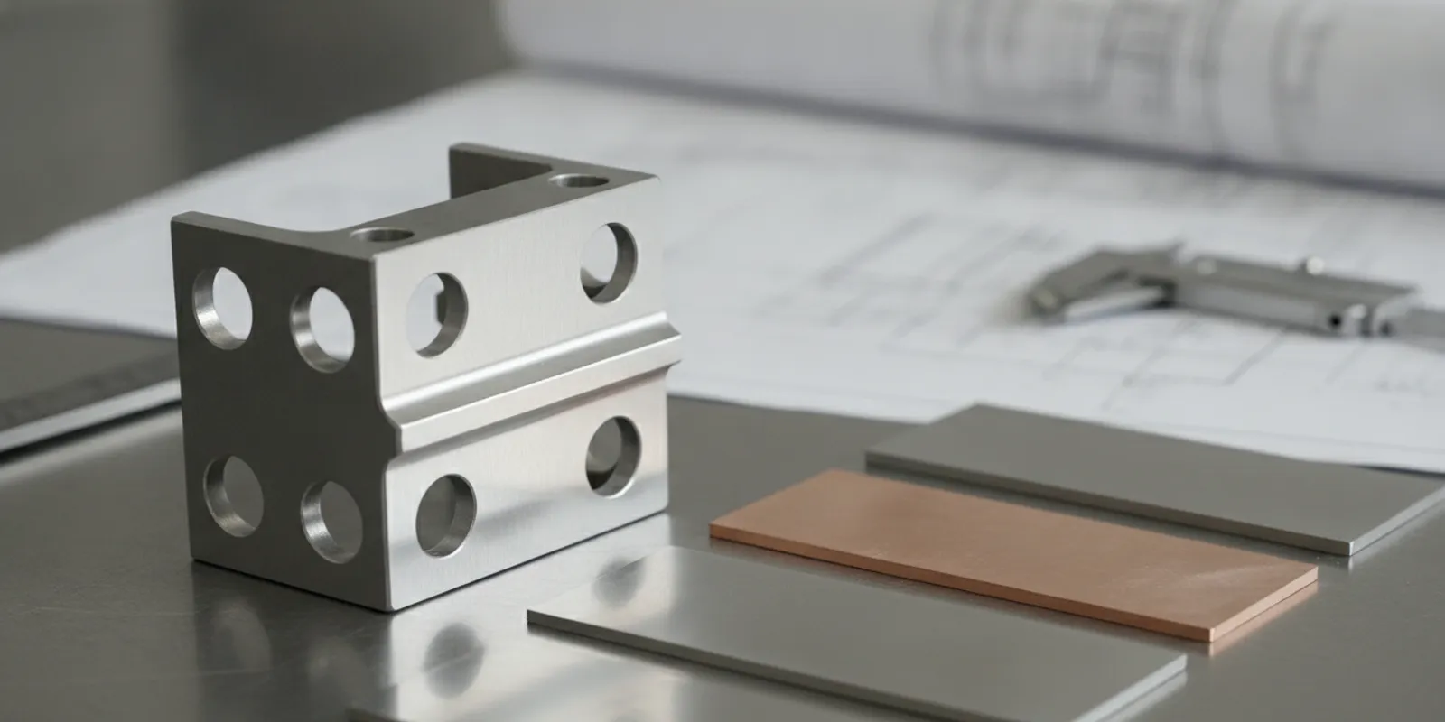
Metal stamping defects are easier to prevent when the part design, material, tooling approach, and inspection plan are considered together. For sourcing, engineering, and program leaders, the goal is not to find a universal rule for every stamped part. It is to make design intent and critical requirements clear enough that a manufacturing partner can assess the process before production. A focused review also helps teams distinguish a true nonconformance from a drawing ambiguity, a measurement difference, or a concern that has not yet been tied to function.
What should a metal stamping design review cover?
A useful review connects the part's function to the way it will be made and checked. A drawing can show the finished shape, but the stamping plan also depends on material, thickness, feature relationships, forming sequence, and how the part is supported and measured. A detail that looks minor in isolation may affect strip layout, tooling, handling, or inspection. Review the whole part in context rather than marking up one dimension at a time.
Before discussing individual features, assemble the information that defines the part:
- The current drawing revision, including units, tolerances, datums, and notes that govern acceptance.
- The material grade or specification, condition when applicable, and thickness with its permitted range.
- The part's function, mating interfaces, load or fit requirements, and surfaces that matter visually or functionally.
- Annual or program volume expectations as a planning range, with assumptions identified.
- Known downstream operations, assembly steps, coatings, or handling requirements that could affect the part.
- Available prototype or production samples, with their revision and any known material or process history.
Keep functional requirements distinct from preferences. If a bend angle, edge condition, flatness, or hole position is critical to assembly, identify it and explain why. If a dimension is reference information, label it accordingly under the drawing standard your organization uses. This helps avoid over-inspecting noncritical details while missing interfaces that determine whether the part works.
Consider writing a short functional note for each critical feature. For example: “This slot locates the bracket against the mating panel; its position controls the assembled gap.” That statement does not replace a dimension or tolerance. It tells the reviewer which relationship matters and invites a useful discussion about the correct datum and inspection method. Repeat this for the few characteristics that drive fit, movement, sealing, electrical connection, or appearance.
How can the drawing make stamping intent clear?
The drawing should define the finished part without leaving two reasonable readers to interpret it differently. Use consistent datums and dimensions, identify the revision, and make material and thickness explicit. Avoid relying on an unreferenced sketch, an old model, or a note that conflicts with a dimension elsewhere in the package. If both a model and drawing are controlled, say how discrepancies are resolved; do not assume that the recipient knows which file takes precedence.
Where the design permits, dimension features from meaningful datums rather than chaining many dimensions from one edge to the next. A long chain can accumulate variation, while a datum scheme tied to assembly function gives the supplier and inspector a more useful reference. The appropriate scheme depends on the part and its fit; there is no one datum layout for every stamping. Ask whether the datums can be contacted or measured consistently on the finished geometry, especially if formed surfaces make a nominally simple reference difficult to establish.
Make edge and surface expectations clear. Identify burr direction or limits when they matter, and call out cosmetic surfaces if appearance is part of acceptance. Show formed views or a three-dimensional model when they clarify the shape, but ensure that the controlled drawing remains authoritative. State whether the model is informational or controlled, and reconcile it with the drawing before release.
Check the drawing package as a set. A material note in one file, a finish callout in another, and an assembly requirement in a spreadsheet can each be correct yet still leave uncertainty about applicability. Use a revision-controlled list to identify the governing files and the relationships among them. If a note applies only after coating or assembly, state that point. If a dimension is measured before a downstream operation, make the sequence explicit so the supplier and receiving inspector are not checking different states.
Which geometry deserves early attention?
Some features are especially useful to discuss before tooling is committed. They are not automatically defects. Their risk depends on material behavior, thickness, geometry, tooling design, and how the part will be produced and inspected. A review should identify the specific question and possible consequence, then determine whether it calls for a design change, a process evaluation, or simply a clearer acceptance rule.
Holes, slots, and edge distance
Hole size, shape, location, and proximity to an edge can influence how a part behaves during forming and whether it remains within required dimensions. A hole near a bend or narrow edge may distort or move relative to the finished geometry. Review the relationship between holes and bends, and identify the holes used for location or assembly. If a feature is critical, put its positional or size requirement on the drawing with a usable datum reference rather than assuming a general tolerance captures the need.
For a bracket with several holes, distinguish the holes that mount the part from holes intended only for clearance. A mounting hole may control alignment with another component, while a clearance hole may allow movement or access. If both are assigned the same tight requirement without a functional reason, the drawing may demand unnecessary control. Conversely, a hole that looks secondary can determine the orientation of the assembly. Describe its role, and ask how it should be checked relative to the formed features.
Bends, flanges, and formed details
Bend geometry depends on material and tooling as well as nominal shape. Tight transitions, short flanges, and closely spaced formed features may constrain tooling or influence springback and final fit. A design review should clarify bend direction, inside and outside surfaces of interest, and dimensions that must be held after forming. Where a flange serves as an assembly interface, specify the relevant finished condition instead of prescribing a process detail without discussing its function.
Consider a flange that must sit against a panel. The important requirement may be the gap after assembly rather than an isolated angle measured on an unsupported sample. The drawing and inspection plan should identify the reference condition that makes the requirement repeatable. If the part is flexible, the team should agree whether it is measured free-state or under a defined support condition; otherwise, two careful inspectors may report different results while following different assumptions.
Cutouts, narrow webs, and tabs
Narrow sections or small tabs may be vulnerable to distortion or damage during processing and handling. Cutouts can also leave thin bridges between features. Assess whether these regions have a clear purpose, whether they need a more robust geometry, and how they will be supported and checked. The right answer may be a geometry change, a different process sequence, or targeted inspection—not necessarily a blanket increase in tolerance.
Trace the load path through a tab or web. Does it locate a second component, retain a fastener, or merely provide clearance? A structural feature may justify careful review of width, corner transitions, and adjacent forming. A nonfunctional remnant may be removable from the design. If the feature must remain, show which edges and dimensions control its role and discuss how samples will be handled so the review itself does not bend a delicate area.
Flatness and overall shape
Flatness requirements should reflect assembly and function. A broad, thin part may respond to forming and handling differently from a compact bracket. Specify flatness where it matters, define the datum or measurement approach needed to make the requirement unambiguous, and discuss how the part is supported during inspection. A number without a consistent measurement condition can create disagreement rather than control.
Think through the part's entire outline as well as local dimensions. A component can meet several individual measurements yet still interfere with a mating part because the overall profile or orientation is not controlled in a useful way. Conversely, a visually imperfect free-state shape may seat correctly in its assembly. The appropriate acceptance condition depends on the product function. Use an assembly fixture, mating component, or clearly defined reference only when it represents the real need and can be reproduced.
How do material and thickness affect the review?
Material is part of the process definition, not a purchasing detail to fill in later. Different grades and conditions can behave differently during cutting and forming. Thickness variation can affect clearances, fit, and relationships between features. If the material specification allows alternatives, identify which are acceptable and whether they have been evaluated against the part's functional requirements.
Do not substitute a generic material label for a complete specification when strength, formability, corrosion behavior, or appearance matters. Share the applicable standard and grade, required condition, and restrictions on substitutions. If the application has environmental or regulatory requirements, state them accurately and ask the prospective supplier how those requirements would be addressed for the particular program. A market served by a manufacturer does not by itself establish a certification or approval.
Material choices should also be reviewed with downstream steps in mind. A finish, joining operation, or assembly can affect which surfaces must be protected and what dimensions must be evaluated after processing. Make clear whether inspection applies before or after those operations, and which party is responsible for each defined step. If a coating changes a fit or a contact surface, identify the finished condition that matters rather than relying on an unstated assumption.
When comparing a proposed material alternative, avoid treating a similar commercial name as proof of equivalence. Compare the governing specification, grade, condition, thickness range, and any requirements tied to the application. Then review which part characteristics might be affected: formed geometry, mating fit, corrosion expectations, or a downstream joining step. The responsible product owner should approve substitutions through the program's change process. A supplier's process suggestion can inform that review, but it does not itself revise the product definition.
What common stamping problems should engineers discuss?
Use defect names as prompts for investigation, not as diagnoses. A visible issue can have more than one cause, and a process adjustment may trade one result for another. When an issue appears in a prototype or production sample, document where it occurs, how often it was observed in the evaluated sample, and whether it affects function or acceptance. Record the observation separately from the suspected cause.
- Burrs or sharp edges: Clarify the permitted edge condition and direction that matters to handling or assembly. Review cut features, tooling condition, and inspection method without assuming one cause.
- Distortion or loss of flatness: Record part orientation, support condition, and point in the process when shape was measured. Compare the result with functional datums and defined acceptance criteria.
- Cracks or splits: Identify location and orientation, then review material specification, local geometry, and forming requirements. Do not accept a material or feature change until its effect on function is understood.
- Wrinkles or uneven formed surfaces: Capture the location and conditions where the feature appears. Review geometry and forming sequence with the supplier, and agree on a way to evaluate the result against a clear requirement.
- Mislocated holes or features: Confirm drawing revision, datum scheme, and measurement approach first. Different references can look like a process problem even when parties are checking different relationships.
- Scratches, dents, or handling marks: Define cosmetic or protected surfaces and the stage at which acceptance applies. Discuss packaging and handling expectations rather than assuming them.
For each concern, distinguish a confirmed nonconformance from a hypothesis. Preserve the affected sample when possible, note the revision and material lot information available, and share photographs that show scale and orientation. A photograph should identify the feature and viewpoint; a close-up without context may show a mark but not where it sits on the part. This gives the supplier discussion a factual starting point without assigning blame before evidence is reviewed.
Use a consistent observation record. Include the sample identifier, date, drawing revision, material information available, measurement method, and the exact requirement being evaluated. State the result and the acceptance limit separately. For a visual concern, describe location, size or extent where practical, and whether the condition affects assembly or appearance. If the condition is intermittent, record the number of pieces examined and the number with the observation; do not turn a small sample into an unsupported production-rate claim.
How should tolerances and inspection requirements be set?
Tolerances should protect function while remaining measurable. Applying a tight tolerance to every dimension can increase inspection burden without improving part performance. Instead, identify critical-to-function features, assembly interfaces, and characteristics tied to safety or compliance requirements. Explain what happens if each one shifts within its allowed range.
When a requirement is important, define how it is evaluated. A dimension may be measured from a datum, checked with a fixture, or verified through another agreed method. The measurement approach should match the feature and the decision being made. If two methods could produce different interpretations, resolve that before approving a production inspection plan. Consider whether the part is supported, how the datum is established, and whether the measurement occurs before or after downstream operations.
Include acceptance criteria for visual conditions where needed. Terms such as “clean,” “smooth,” or “no defects” may be too open-ended on their own. Add a defined area, condition, reference sample, or measurable threshold where appropriate to the product and buyer's quality system. The specific criteria must come from the product owner and applicable requirements, not from an assumed default.
A helpful approach is to divide drawing characteristics into three practical groups for discussion. First are characteristics that directly control fit or function and need explicit evaluation. Second are characteristics that are useful for process monitoring but may not need a restrictive product tolerance. Third are reference details that describe the design without controlling acceptance. This is a working conversation aid, not a substitute for the applicable drawing standard or quality system. The goal is to make the reason for each control visible.
For example, a formed bracket might have a critical mounting-hole relationship, a bend surface that must seat against a panel, and a nonfunctional outside edge. The mounting relationship could receive a defined datum-based location requirement. The seating surface could have a stated flatness or assembled condition if that is what function requires. The outside edge might be controlled by a general profile requirement and a clear edge condition. That arrangement is more informative than applying the tightest tolerance everywhere and hoping the inspection plan infers priorities.
What belongs in a stamping RFQ package?
A complete request helps a prospective manufacturing partner identify questions early. Keep controlled files organized, label revisions, and state which file takes precedence if the drawing and model do not agree. If the package includes confidential product information, use the secure submission method and terms agreed with the recipient rather than placing sensitive files in an unapproved channel.
- Part drawings and controlled models, with revision and units identified.
- Material specifications, finish requirements, and permitted substitutions.
- Critical dimensions, datums, inspection expectations, and acceptance criteria.
- Expected volume range, demand pattern, and forecast assumptions for evaluation.
- Assembly context, mating parts, and photos or samples that explain interfaces.
- Known quality, packaging, labeling, or documentation requirements.
- Open design questions and a list of assumptions that the supplier should confirm.
- Known downstream operations and the condition in which the part is accepted.
Ask the supplier to separate what is known from what remains to be evaluated. A useful response can identify design questions, tooling assumptions, inspection considerations, and exclusions. Do not treat an early estimate or process discussion as a production commitment unless scope, requirements, and commercial terms have been agreed through appropriate channels.
Before sending the package, run a simple release check. Open each file and confirm that the revision stated in the file matches the package index. Check that units are consistent, material and thickness are present, and any referenced standards are identified. Compare the drawing and model for obvious conflicts. Confirm that critical features are clearly marked and that the request explains whether the supplier is being asked to evaluate manufacturability, provide a quote, review a sample, or address all three.
When the program is early, label estimates and assumptions as provisional. A concept drawing without final material or volume information may still support an initial conversation, but the missing inputs should be visible. List the questions that remain open and assign an owner for resolving each one. That makes it easier to compare supplier responses on the same basis and reduces the risk that one proposal quietly assumes a different scope from another.
How do tooling and production planning fit together?
Tooling is closely connected to part geometry, production expectations, and process route. A design that has not been reviewed for manufacturability may require revisions after tooling discussions begin. Bring the intended function and critical requirements to that discussion, and ask which features drive tooling complexity or require a design decision. The objective is not to prescribe a tool design from the buyer's side; it is to surface the requirements and assumptions that influence a viable route.
EMS Technologies describes metal stamping among its manufacturing capabilities and presents engineering and program management as support across the manufacturing lifecycle. The company also describes a Taiwan development and test-series path followed by transfer to China for production for suitable smaller complex tooling projects; that path is specific to the projects described and is not a universal routing rule. Ask how a proposed route applies to your program, which organization or site performs each step, and what information is needed at each handoff.
For a program involving a test series, agree what the test is intended to establish. Is the team checking whether the geometry can be produced, whether critical dimensions meet the drawing, whether the part fits the assembly, or whether handling and packaging are adequate? These are related but distinct questions. A sample approval should identify which questions have been answered and which remain open. Do not treat a successful sample for one purpose as automatic approval of every downstream requirement.
For buyers considering multiple process capabilities, the relevant question is how the full component or assembly will be coordinated. The markets served overview can help identify whether the intended end market is among the company's stated areas of work. If the part includes wiring or an electrical interface, review the cable assemblies and wire harnesses capability as a separate scope to discuss, rather than assuming it is included in a stamping quote.
How can buyers evaluate a supplier's response?
Look for evidence that the supplier understood the controlled design and the way the part will be used. A useful technical conversation should surface ambiguities, identify assumptions, and distinguish confirmed requirements from proposals. It should also address how the part will be checked and how changes will be managed. A polished capability statement does not answer program-specific questions on its own.
Consider asking:
- Which drawing details need clarification before a process route can be evaluated?
- How will critical features be referenced and inspected?
- What material, tooling, or geometry assumptions are being made?
- Which processes or locations are proposed for this program, and what handoffs should the buyer understand?
- How will revisions, sample feedback, and approval records be controlled?
- Which packaging, labeling, or downstream assembly requirements belong in the scope?
- What information is still needed before the supplier can confirm the proposed approach?
Evaluate answers against your program's requirements, not generalized claims. Ask for relevant process and quality information for the actual proposed scope. For a broader checklist on evaluating an electronics supplier, see how to choose an electronics contract manufacturer; use it as complementary guidance, since it does not replace a stamping-specific technical review.
Compare responses on a shared question set. One supplier may ask for a controlled model, another may focus on material condition, and a third may flag inspection access. Those differences can reveal useful questions, but they should not be mistaken for a direct comparison unless each response addresses the same part revision and scope. Keep a register with the question, the answer, the supporting document, and the owner who will decide whether a proposed change is acceptable.
What should happen after a sample review?
Close the loop with a documented decision. Record the drawing revision, sample identity, material information available, inspection results, open issues, and disposition. If a design change is approved, update controlled files and communicate the effect on related dimensions, tooling, and inspection. Do not rely on an email description alone when the product definition itself needs to change.
Separate temporary containment from permanent corrective action. If a sample does not meet an agreed criterion, first establish what is affected and what decision is needed for the program. Then review the cause with the supplier using evidence. A correction should be verified against the same requirement that identified the issue, and any change to the acceptance plan should be approved by responsible product and quality owners.
A sample review record can be concise while still being useful. Identify the date and participants, the part and revision, the sample quantity reviewed, the inspection method, the requirements evaluated, and each finding. For each finding, state whether it is accepted, rejected, awaiting more information, or assigned for follow-up. Attach marked-up photographs or measurement records where they clarify the decision. Assign an owner and due point for each open question without implying a supplier lead time that has not been agreed.
Before releasing a revised package, verify that the change is complete across all affected files. A hole shift may affect a mating component, inspection fixture, assembly instruction, or packaging orientation. A change in material may alter more than a purchasing line. Review the impact with engineering, quality, sourcing, and program stakeholders as appropriate, then issue one clear revision package. Retire superseded files from active use or mark them clearly so old information does not re-enter the build.
Prepare for a focused manufacturing discussion
A strong stamping design review begins with a controlled drawing, a clear material specification, and a short list of requirements that matter to product function. Use likely defect modes to guide questions, then confirm the actual conditions and acceptance criteria for your part. With those basics prepared, a sourcing or engineering team can have a more specific discussion about tooling, process fit, inspection, and program coordination.